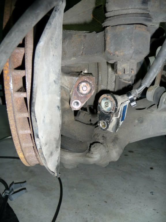
I'm writing this guide up as I can't find anything similar on here or any other Toyota related forums. I'll double-post this across to Celicatech.com just in case this post gets lost/forum goes down/etc. This is a guide on how to change the 4WS (four wheel steer) front left-hand speed sensor as fitted to a 1992 Celica Convertible ST183. The 4WS system is fitted to a number of Toyota models so this may or may not be of use to others. Using the fault guide (check subsequent posts below) I was given error code 41, speed sensor fault. Upon investigation mine was in two pieces:
As well as a how-to-do-it its also a how-to-save-money guide, not only because if you DIY you'll save money but also because if anyone has checked out the OEM cost of a replacement speed sensor its pretty steep. I was quoted an initial price of $640NZ (£240) from the main dealer who went away and came back with a 'better' price of $325NZ (£125) - still too much for a tight git like me! So, on to the internet and an evening spent trawling forums and online parts distributors revealed two things...firstly no-one makes a 4WS speed sensor for a 1992 Celica. Secondly, a lot of the 4WS models also have ABS (mine doesn't). Now it seemed unlikely to me that the ABS sensor and the 4WS speed sensor would be different or seperate...they both do exactly the same job i.e. count teeth on the wheel hub to determine wheel speed. Some online info stated the 4WS controller looks for a sensor output of between 50-700mV AC which is a pretty large range to work with as well, further reinforcing my belief that an alternative option might work. So, I looked for a speed sensor that was physically similar looking, from a model of around the same year of manufacture and that might also be fitted with ABS. I came up with the 1992 Toyota Camry although further research shows the Camry sensor is also fitted to the Avalon, Solara and Lexus ES300! So, it looked physically similar....
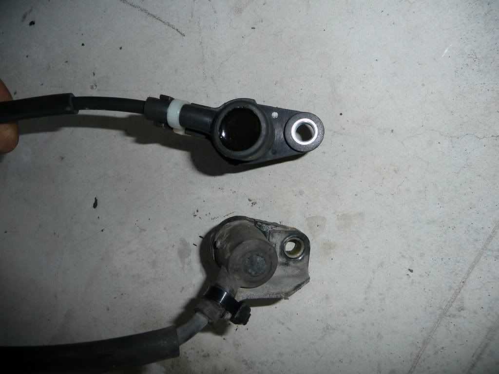
...and I found a seller on Ebay (automartint914) with brand new ones for $49.95US with $20US shipping charge to New Zealand - so around $100NZ - cool! The part is made by RAYBESTOS p/n ABS530165 but is also made by Standard p/n ALS267 and by Wells p/n 72-6011.
So, down to the guide. I'll skip detailing the obvious stuff like the fact you need to jack the car up and put it on blocks or stands, remove the L/H front wheel and turn the steering to full right lock for access. Also, when I refer to a 10mm bolt, i'm talking head size not thread size (for the pedants out there).
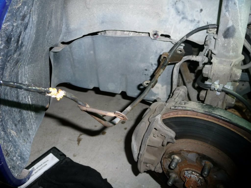
The wheel arch liner has a 10mm bolt at the top near to where the speed sensor loom goes, remove the bolt, peel back the liner a bit and unclip the loom. Next, undo the two 10mm bolts that hold the speed sensor metal loom carrier to the inside of the wheel arch. Then undo the 10mm bolt that holds the second speed sensor loom bracket to the brake pipe bracket on the side of the suspension strut:
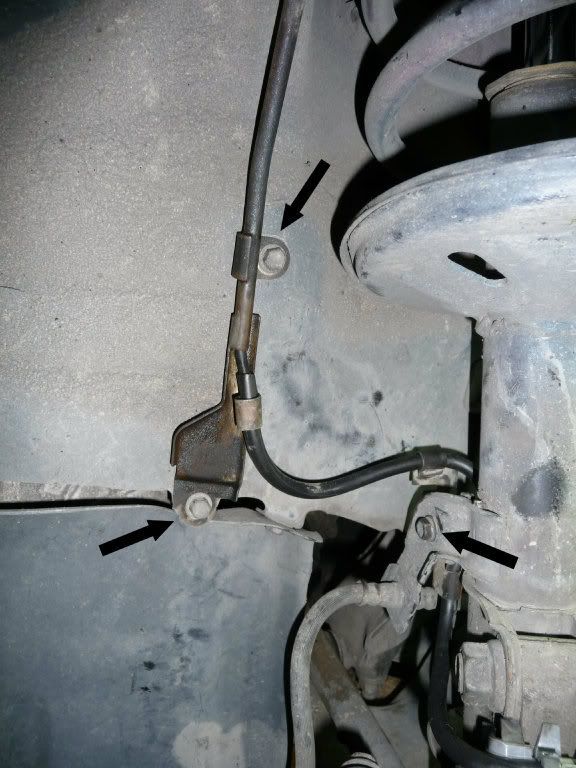
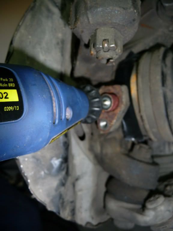
Finally undo the 10mm bolt that holds the speed sensor to the wheel hub - not strictly necessary in my case as you can see above ;-) Ok, so thats the loom and the remains of the sensor removed. If your sensor is still whole but not working then get a set of stilsons or pipe wrench pliers and attempt to twist it from the hub....you may be lucky or it may snap off. I had to drill mine out. I just used a cordless drill and a 3mm drill bit to drill around the centre metal stud into the copper wire of the sensor. Drill a bunch of holes, lever out the remains of the copper with a small screwdriver and you should then be able to pull the centre stud of the sensor out with some thin-nosed (snipe-nosed) pliers. Then just break the rest of the sensor up with the small screwdriver/pliers and it will eventually just pull out. WORD OF WARNING: when drilling only drill to about 15mm depth (or half inch-ish) - you dont want to risk hitting the toothed wheel on the hub or its protecting ring! So sensor is out:
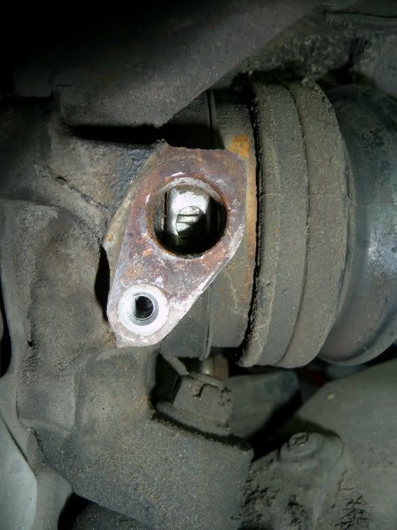
Next clean out the hole with some emery paper/grit paper/sand paper/whatever. I used a dremel type tool with a sanding attachment. Cover the small window in the toothed wheel protection ring first so all the crap doesn't go inside though! I just used a bit of tape:
Ok, so now the new sensor should slide easily into the nice clean hole:
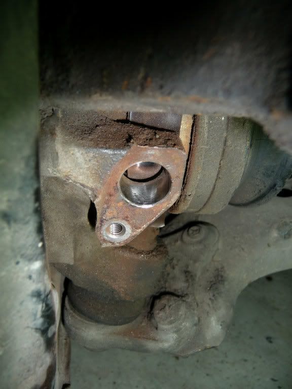
So, to the sensor itself. I measured the depth of the hole to the toothed wheel and then the sensor to ensure nothing was going to foul...it was spot on!
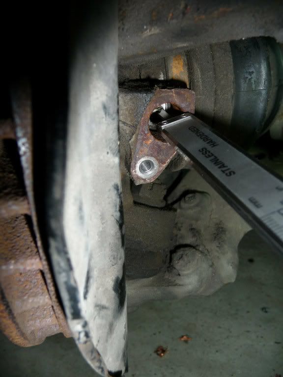
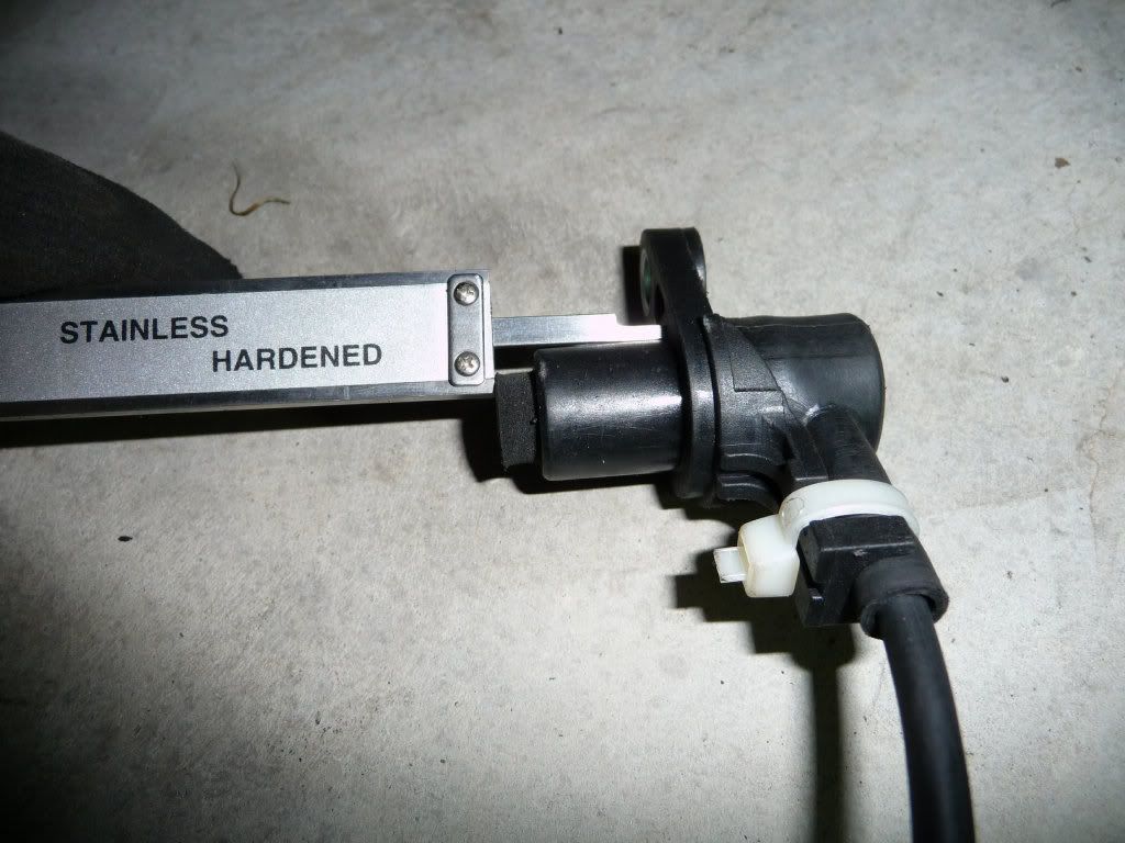
Now, the sensor loom needs some slight modification as the bracketry and connecting plug are different:
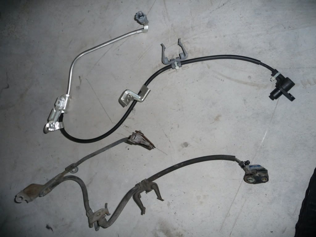
The U-shaped clip nearest the sensor is identical and should fit back exactly where the old one did. The bracket that fixes onto the suspension upright is different and needs to be changed, this is a piece of cake. Simply insert a screwdriver into the gap....
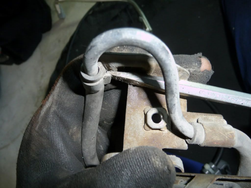
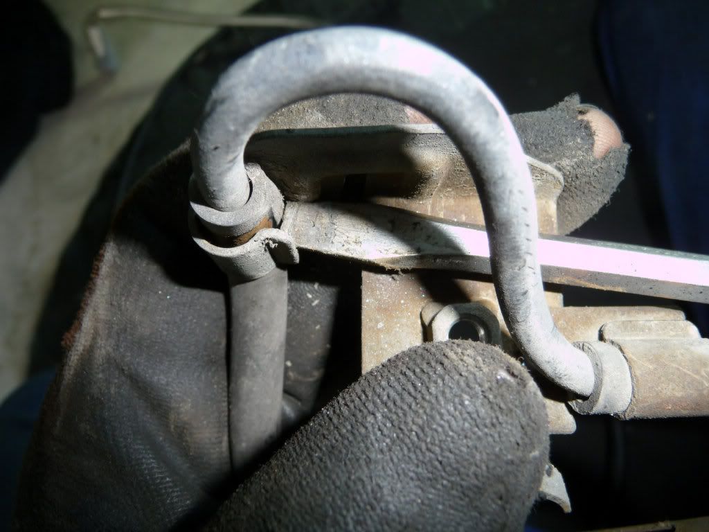
...and twist to enlarge it enough to remove the old loom. Insert the new loom and close the clip back down with pliers.
The metal loom carrier is a bit more fiddly. You could just cut the plug off, unthread the loom from the old metal loom carrier (its basically a bit of bent pipe and the loom goes inside it for protection), thread the new loom through the old carrier and just crimp the new loom back into the car wiring when its fixed into place but that seemed a bit quick 'n' nasty to me. The pins in each plug are the same, only the plug is different:
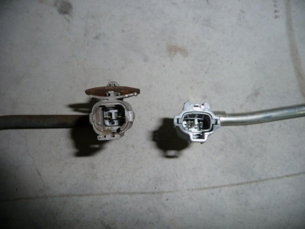
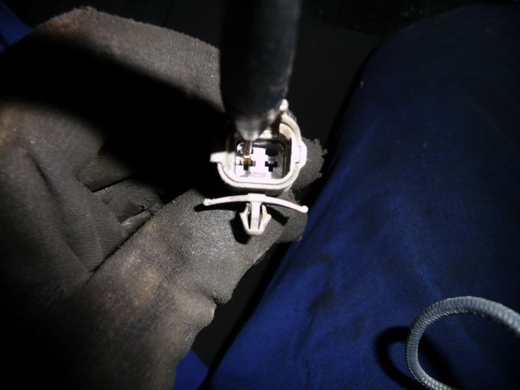
If you look into the open end of the old plug, you will see two pins. Each pin has a little plastic lip holding it in...a fine screwdriver inserted between the pin and the lip will bend the lip back and allow you to withdraw the pin by pulling its wire from the other end:
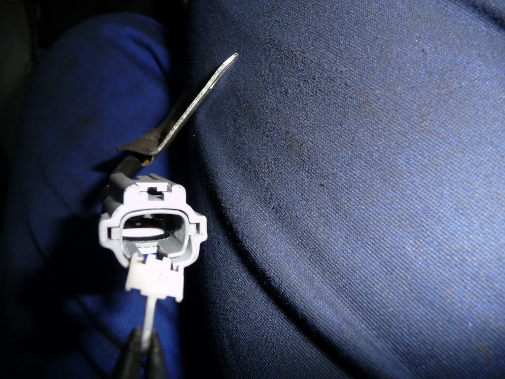
The new loom connector is slightly different, it has a white plastic clip that needs to be removed first. Simply pull this out with thin-nosed pliers from the open end of the plug and you can then remove the pins as before:
I then threaded a piece of old wire down the metal carrier pipe, taped it to the new loom and pulled it back through, pins and all. It wasn't quite that simple though and required several attempts to get the pins in just the right place so the overall taped up bundle wasn't too wide to fit in the pipe. A bit of wd40 helps ease the journey.
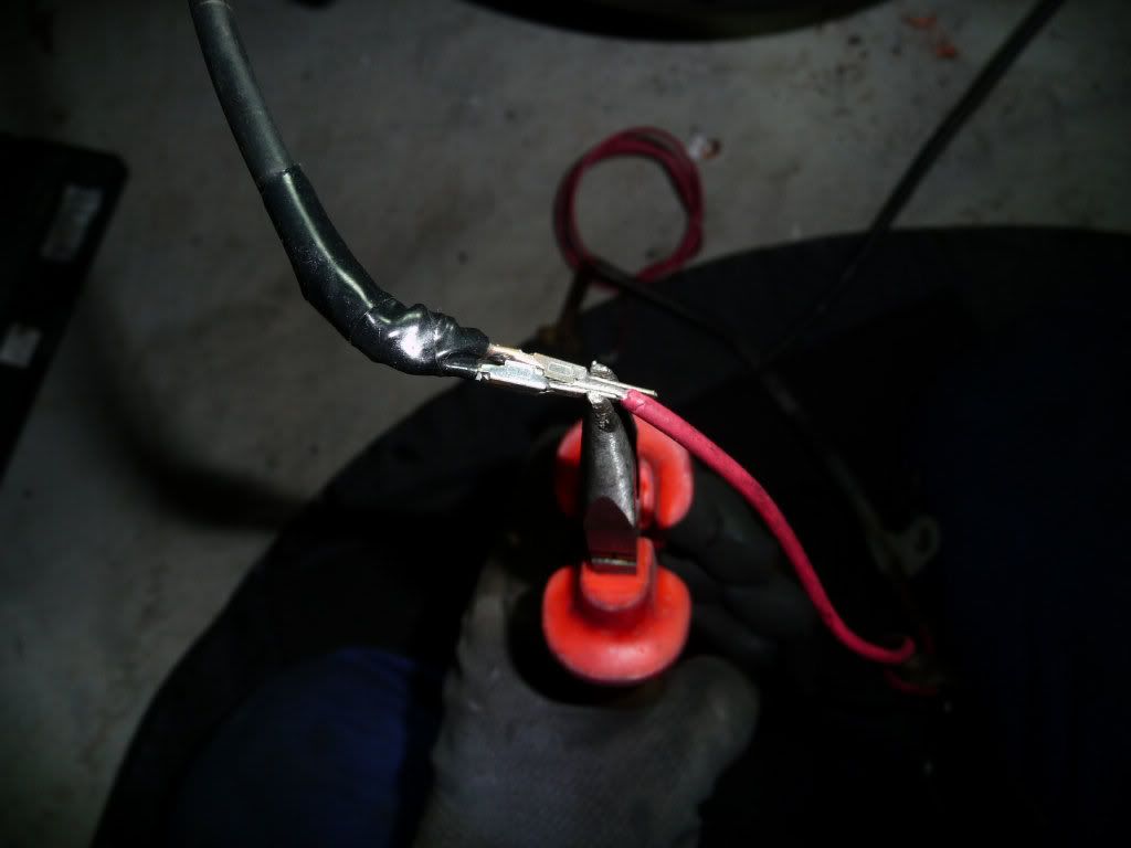
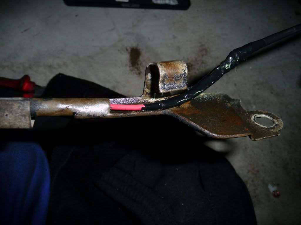
The old sensor and new sensor wiring colours are different but just ensure that the common grey wire goes back into the same place on the plug. Simply orientate the pins so that when you push the new pins into the old plug they line up internally and they will snap back into place - easy! You can now refit the loom and brackets back into place and reconnect it back into the car loom.
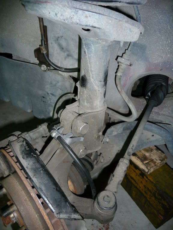
Refit the wheel arch liner bolt and after a final check to ensure the speed sensor and loom dont foul on anything, refit the wheel and go for a test!
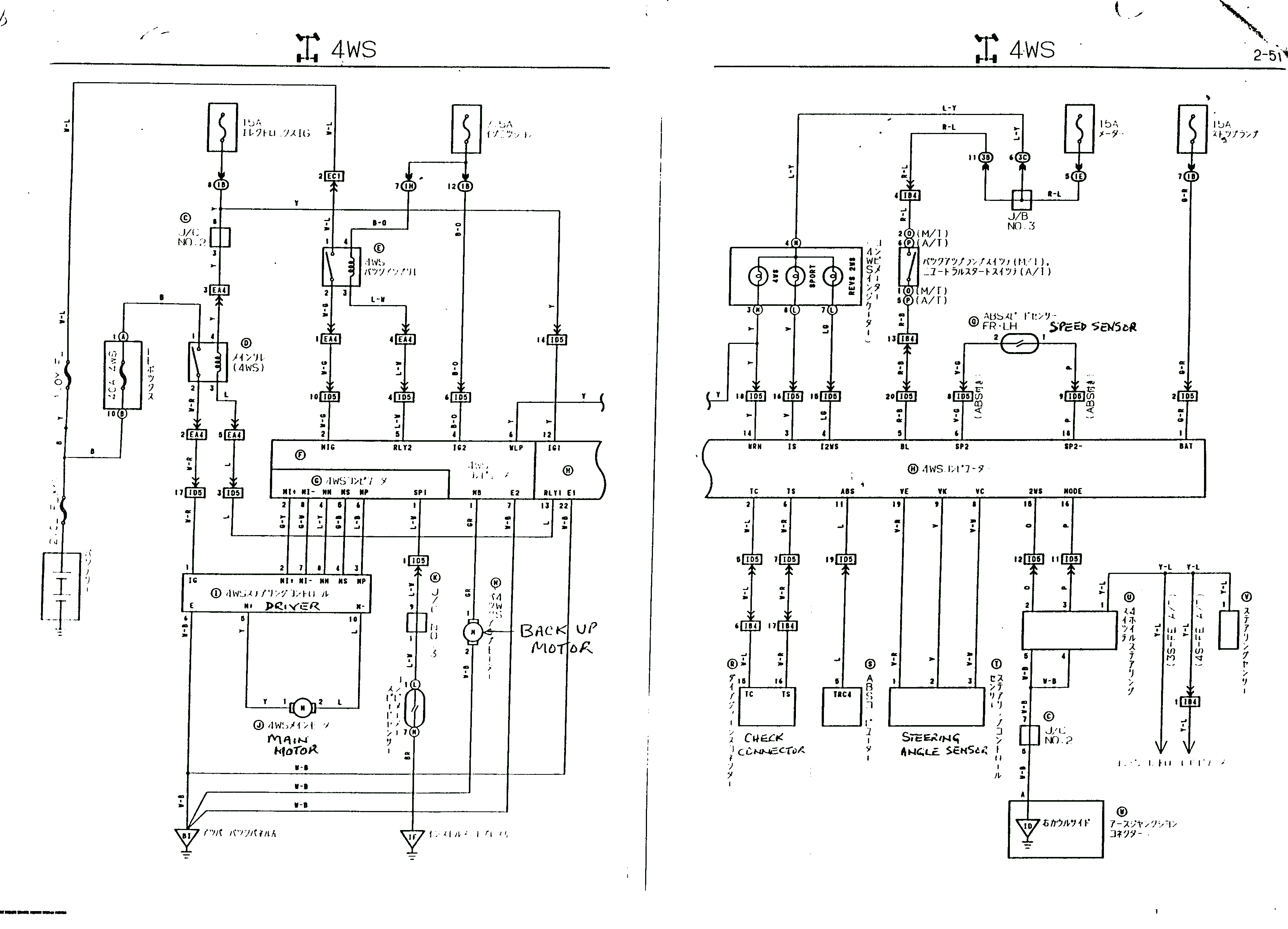
I've also taken the liberty of posting all of the 4WS information that I managed to aquire from this forum and elsewhere into the following posts. Hopefully this will prove useful :-)
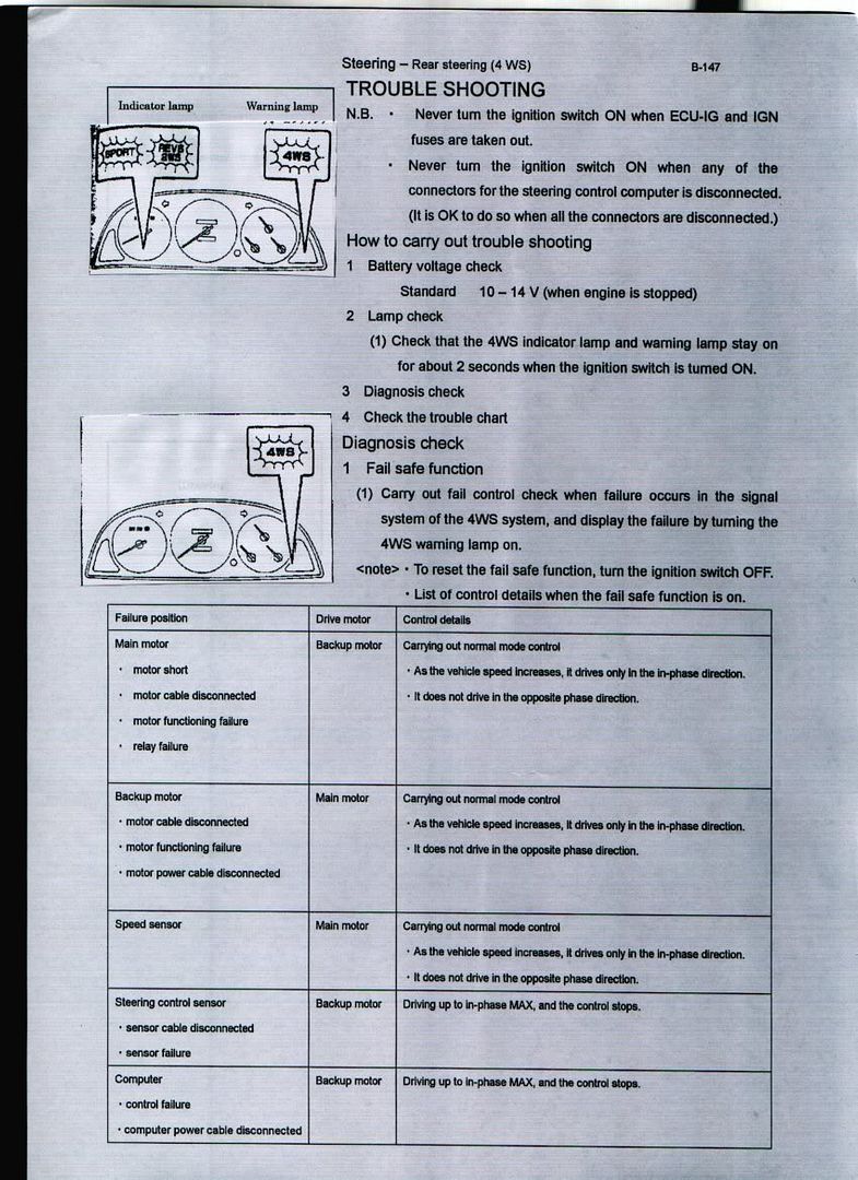
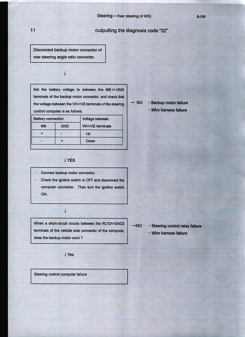
4WS instructions, fault codes and schematic:
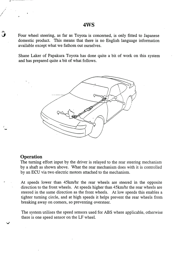
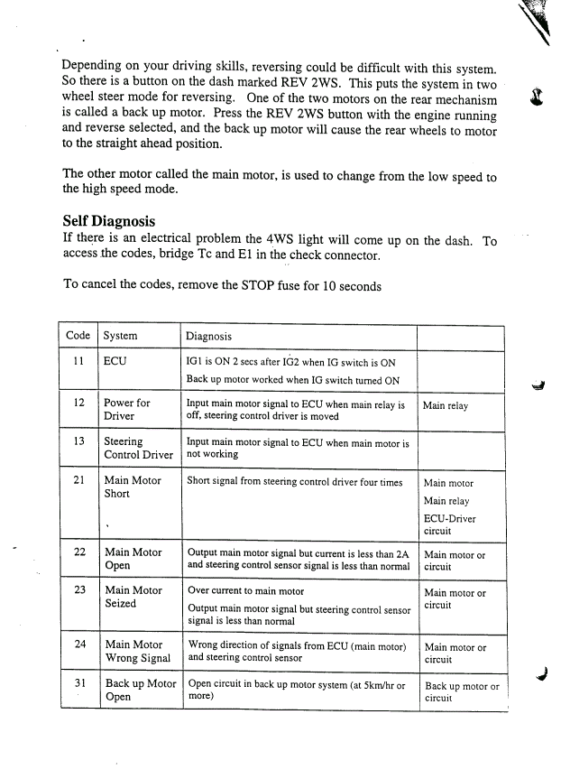
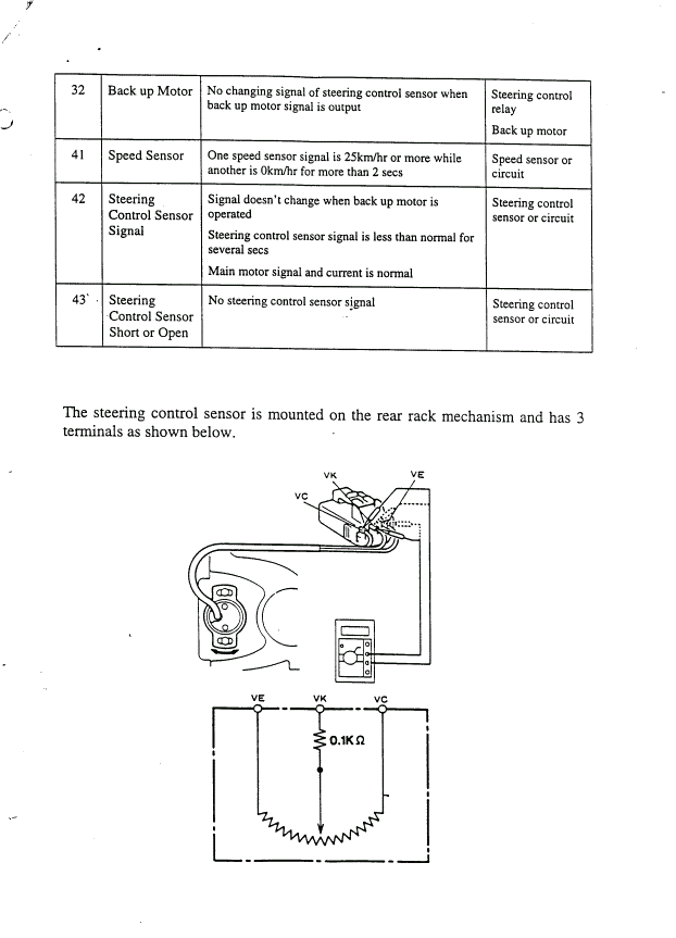
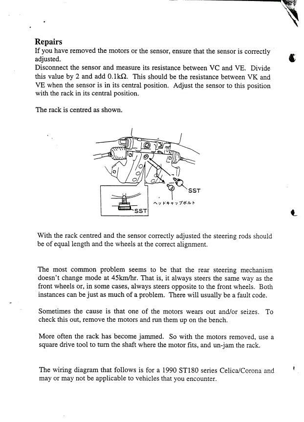
A video file created by another user (sorry, didn't take your name!) showing how the 4WS spherical bearing works:
http://s33.photobucket.com/albums/d99/oran...current=4ws.flv
And finally, all 64 pages of the Japanese 4WS manual:
http://s33.photobucket.com/albums/d99/oran...S/Jap%20manual/
Everything listed above available on rapidshare:
http://rapidshare.co...7558909/4WS.rar
Password for above is 'orange' without the quotes ![]()

