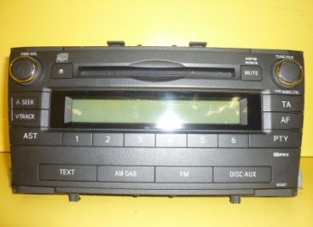
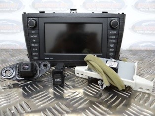
How to replace a Toyota Avensis (T27) Radio/CD player W53828 with a Toyota navigation unit B9012
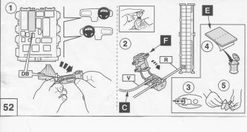
First disconnect the vehicle battery.
There is a 20 pin connector plugged into the back of Radio/CD W53828 with the following pin out:
1. Empty
2. Empty
3. Yellow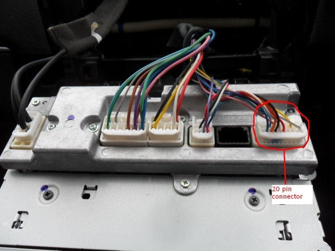
4. Empty
5. Empty
6. Purple
7. Pink
8. Light Blue
9. Empty
10. Empty
11. White & Black
12. Empty
13. Empty
14. Empty
15. Red
16. White
17. Black
18. Orange
19. Dark Blue
20. Empty
Next there is an 8 pin connector plugged into the back of Radio/CD W53828 with the following pin out: (this connector will not plug into the back of the Toyota Navigation unit B9012)
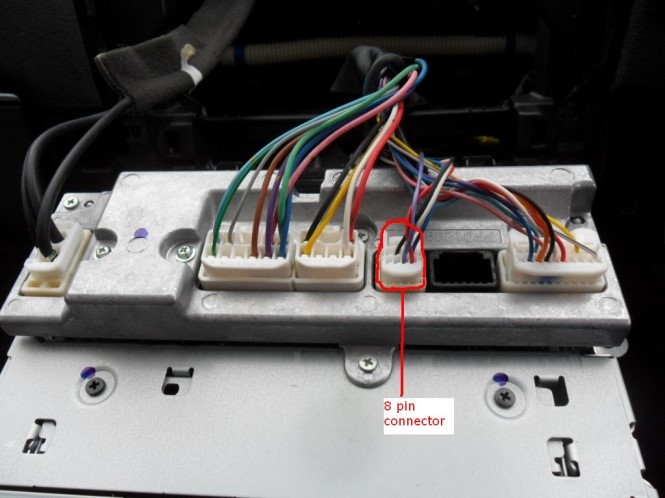
1. Blue
2. White
3. Black
4. Empty
5. Red
6. Purple
7. Empty
8. Empty
The other connections are the same in both units.
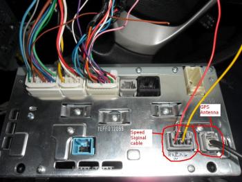
If you only have the Toyota Navigation unit B9012 without any of the connectors you will have to buy a speed signal cable (€10 approx.) that fits into the grey connector on the B9012, part No. PZ445-00333-04 and a GPS antenna (€25 approx.), part No. PZ445-00333-05.
The GPS antenna will fit directly into the back of the B9012. If you bought the speed signal cable from a Toyota Dealer it will have 3 wires (Red, Purple & White, and Green). If you got it from a donor car it will have 2 wires (Red wire and a Yellow wire).
Cut the Yellow wire that goes to pin 3 of the 20 pin connector. Connect the end that is coming from the vehicle wiring harness to the purple & white cable of the speed signal cable you purchased (or the yellow wire if you got it from a donor car).
The yellow wire that is still attached to the 20 pin connector must be connected to the blue wire that is in pin 1 of the 8 pin connector.
Then make the following connections:
Move the white wire in pin 2 of the 8 pin connector to pin 4 of the 20 pin connector.
Move the black wire in pin 3 of the 8 pin connector to pin 5 of the 20 pin connector.
Move the red wire in pin 5 of the 8 pin connector to pin 13 of the 20 pin connector.
Move the purple wire in pin 6 of the 8 pin connector to pin 14 of the 20 pin connector.
You should now have all the Bluetooth and navigation functionality on the B9012 unit and in the proper place on the steering wheel controls.
Now the Rear View or Reverse camera.
If you got a rear view camera the connector for it is already inside the panel in the boot lid. However this cable only goes up as far as a grey block connector inside the left hand kick panel beside your left leg in the foot well of the passenger seat (in the case of a RHD). The connector in the boot lid will have 4 wires inside a black outer casing - White, Red, Black, and Blue. The insulation on the blue wire may only extend up the cable a few centimetres. At the other end inside the kick panel it may have orange or green insulation. This wire needs to be extended from here up to the back of the Toyota navigation unit B9012. At the back of the Toyota navigation unit B9012 make the following connections:
Red wire to pin 1 of the 20 pin connector.
Black wire to pin 2 of the 20 pin connector.
White wire to pin 11 of the 20 pin connector (there is already a white & black wire in this position, remove it and insulate the end of it).
Blue (Orange or Green) to pin 12 of the 20 pin connector.
Now extend the red wire from the speed signal cable connector down to the back of the glove box.
Behind the glove box there is a panel with various block connectors, relays, fuses etc. On this panel three of the block connectors are held in with black clips over the block connectors. The middle one of these block connectors has a red wire near the bottom. This is the reverse signal cable. Connect the red wire from the speed signal cable to this wire.
Your reverse camera should now work.

